- 您现在的位置:买卖IC网 > Sheet目录2007 > MAX1104EUA+ (Maxim Integrated Products)IC CODEC 8BIT 8-UMAX
DAC Continuous Conversion Mode
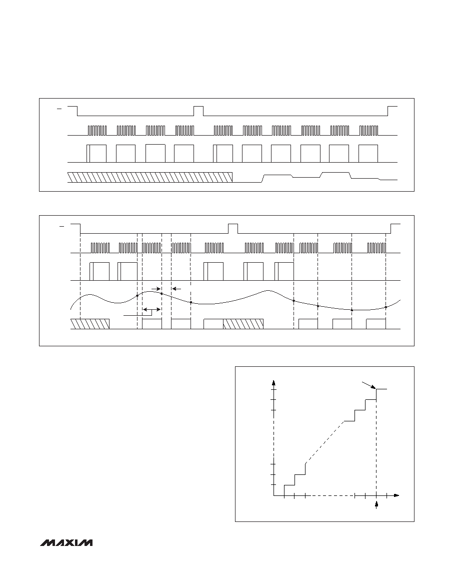
Once the DAC is configured in continuous conversion
mode, the analog output, OUT, is updated at the rising
edge of every eighth clock pulse (Figure 7). To exit
DAC continuous conversion mode, toggle CS. The
device requires a new control word before any further
conversions take place.
ADC Continuous Conversion Mode
Set C0 = 1 to select continuous conversion mode. The
falling edge of SCLK after the eighth bit of the control
word causes the ADC to switch from track to hold
mode and begin conversion. To avoid corruption of the
conversion result, SCLK must be disabled for 36s
(Figure 8). After completing the conversion, the ADC
automatically returns to track mode, and the next eight
clock cycles shift out the result on DOUT. The falling
edge of SCLK during the eighth bit of the result will
again cause the ADC to switch from track to hold mode
and begin the next conversion.
MAX1102/MAX1103/MAX1104
8-Bit CODECs
______________________________________________________________________________________
13
SCLK
OUT
CS
S
DAC
ADDR
DAC OFF
S
DAC
ADDR
DAC ON
DAC
DATA
DAC
DATA
DAC
DATA
DAC
DATA
DAC
DATA
DAC
DATA
DAC
DATA
DAC
DATA
DIN
Figure 7. DAC Continuous Conversion Mode Timing Diagram
SCLK
AIN
DOUT
CS
SS
ADC
ADDR
ADC ON
S
ADC
ADDR
ADC ON
S
ADC
ADDR
ADC ON
ADC
ON
S ADC
ON
DIN
1
2
3
tCONV
MSB LSB
CONVERSION
RESULT FOR 1
T/MIN ACQUISITION
MODE
MSB LSB
CONVERSION
RESULT FOR 2
MSB LSB
CONVERSION
RESULT FOR 3
MSB LSB
CONVERSION
RESULT FOR 4
MSB LSB
CONVERSION
RESULT FOR 5
MSB LSB
CONVERSION
RESULT FOR 6
4
5
6
7
Figure 8. ADC Continuous Conversion Mode Timing Diagram
OUTPUT CODE
FULL-SCALE
TRANSITION
11111111
11111110
11111101
00000011
00000010
00000001
00000000
0.5 1.5 2.5
0
FS
FS - 1.5LSB
INPUT VOLTAGE (LSB)
(IN-)
Figure 9. ADC Input/Output Transfer Function
发布紧急采购,3分钟左右您将得到回复。
相关PDF资料
MAX11100EUB+
IC ADC 16BIT SRL 200KSPS 10UMAX
MAX11101EUB+
IC ADC 14BIT SRL 200KSPS 10UMAX
MAX11102AUB+
IC ADC 12BIT SPI/SRL 10UMAX-EP
MAX1111CPE+
IC ADC 8BIT LP 16-DIP
MAX1113CPE+
IC ADC 8BIT LP 16-DIP
MAX1116EKA+T
IC ADC 8BIT SERIAL SOT23-8
MAX11201BEUB+T
IC ADC 24BIT SRL 13.75SPS 10UMAX
MAX11202BEUB+T
IC ADC 24BIT SRL 13.75SPS 10UMAX
相关代理商/技术参数
MAX1104EUA+T
功能描述:ADC / DAC多通道 8-Bit CODEC RoHS:否 制造商:Texas Instruments 转换速率: 分辨率:8 bit 接口类型:SPI 电压参考: 电源电压-最大:3.6 V 电源电压-最小:2 V 最大工作温度:+ 85 C 安装风格:SMD/SMT 封装 / 箱体:VQFN-40
MAX1104EUA+TW
功能描述:ADC / DAC多通道 8-Bit CODEC +2.7V to +5.5V Single Supply RoHS:否 制造商:Texas Instruments 转换速率: 分辨率:8 bit 接口类型:SPI 电压参考: 电源电压-最大:3.6 V 电源电压-最小:2 V 最大工作温度:+ 85 C 安装风格:SMD/SMT 封装 / 箱体:VQFN-40
MAX1104EUA+W
功能描述:ADC / DAC多通道 8-Bit CODEC +2.7V to +5.5V Single Supply RoHS:否 制造商:Texas Instruments 转换速率: 分辨率:8 bit 接口类型:SPI 电压参考: 电源电压-最大:3.6 V 电源电压-最小:2 V 最大工作温度:+ 85 C 安装风格:SMD/SMT 封装 / 箱体:VQFN-40
MAX11054
制造商:MAXIM 制造商全称:Maxim Integrated Products 功能描述:4-/6-/8-Channel, 16-/14-Bit, Simultaneous-Sampling ADCs
MAX11054ECB+
功能描述:模数转换器 - ADC 14Bit 4Ch Simult Sampling RoHS:否 制造商:Texas Instruments 通道数量:2 结构:Sigma-Delta 转换速率:125 SPs to 8 KSPs 分辨率:24 bit 输入类型:Differential 信噪比:107 dB 接口类型:SPI 工作电源电压:1.7 V to 3.6 V, 2.7 V to 5.25 V 最大工作温度:+ 85 C 安装风格:SMD/SMT 封装 / 箱体:VQFN-32
MAX11054ECB+T
功能描述:模数转换器 - ADC 14Bit 4Ch Simult Sampling RoHS:否 制造商:Texas Instruments 通道数量:2 结构:Sigma-Delta 转换速率:125 SPs to 8 KSPs 分辨率:24 bit 输入类型:Differential 信噪比:107 dB 接口类型:SPI 工作电源电压:1.7 V to 3.6 V, 2.7 V to 5.25 V 最大工作温度:+ 85 C 安装风格:SMD/SMT 封装 / 箱体:VQFN-32
MAX11055
制造商:MAXIM 制造商全称:Maxim Integrated Products 功能描述:4-/6-/8-Channel, 16-/14-Bit, Simultaneous-Sampling ADCs
MAX11055ECB+
功能描述:模数转换器 - ADC 14Bit 6Ch Simult Sampling RoHS:否 制造商:Texas Instruments 通道数量:2 结构:Sigma-Delta 转换速率:125 SPs to 8 KSPs 分辨率:24 bit 输入类型:Differential 信噪比:107 dB 接口类型:SPI 工作电源电压:1.7 V to 3.6 V, 2.7 V to 5.25 V 最大工作温度:+ 85 C 安装风格:SMD/SMT 封装 / 箱体:VQFN-32